Archived Microtan manual
Microtan 65 system manual
Surviving chapters of the original Microtan 65 system manual.
This manual was scanned and converted by optical character recognition by Fabrice Frances. The legacy HTML contains chapters 3 and 6, followed by part of the TANBUG listing; chapters linked but absent from the source are recorded below.
Contents represented in the source
CHAPTER 1 Microprocessors and Binary Numbers CHAPTER 2 Contructional Notes CHAPTER 3 The Microtan 65 CHAPTER 4 The Microtan System CHAPTER 5 The 6502 Microprocessor. Tables of Machine Instructions. CHAPTER 6 Using TANBUG. Tables of Hex ASCII Codes. TANBUG Listing. CHAPTER 7 Some Games Programs.
Foreword
Unlike most other microcomputers, microtan 65 has been designed from the start with a small system in mind, therefore expansion of microtan 65 is a concept, not an afterthought. We hope that this manual will be the first of many, as each Tangerine product is supplied with thorough and useful documentation, an absolute necessity with anything related to computers. The first chapter of this manual provides an introduction to microprocessors and the binary number system, it is by no means complete as this subject requires a complete book to be dedicated to it. Chapter two gives constructional notes for the kit version but purchasers of ready built microtan 65’s are still advised to read it as it contains relevant information. Chapters three and four describe the microtan 65 and the microtan system respectively. The 6502 microprocessor is described in sufficient detail in chapter five which also contains complete tables of all of the 6502 machine code instructions. TANBUG, the most important item, is fully described in chapter six with a step by step guide and an example program to demonstrate the power of TANBUG’s debugging aids. Also given in chapter six is a table of hex ASCII codes and the complete TANBUG listing. Games programs have been provided in chapter seven.
CHAPTER 3: The Microtan 65
The microtan 65 is an exceptional microcomputer kit and the purpose of this section is to describe its design. It was considered that the majority of microkit users would initially benefit from a machine that was very easy to use rather than one that has parallel I/O, but was very awkward to use. Therefore microtan 65 is supplied with a VDU on-board, and because of this the ability to use an alphanumeric keyboard is an immediate asset. The 6502 microprocessor was chosen mainly for its very simple yet elegant hardware structure. Of course, as most readers will know, the 6502 also has a very powerful instruction set and addressing modes.
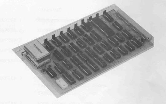
A fully expanded microtan 65 contains the 6502 microprocessor, 1K rom containing TANBUG, 1K RAM which is used for display memory and user program, keyboard interface, VDU logic and tri-state address buffers. The basic block diagram of the microtan 65 is shown below.
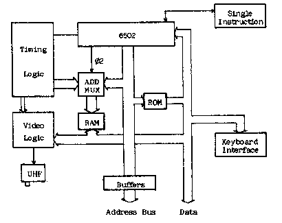
The most important aspect of the design is that the address multiplexer is switching at the processor clock rate. This can be done with the 6502 as memory accesses will only occur on one phase of the clock i.e. when 02 is high. When 02 is low the memory is not selected. During this time the VDU logic reads the display memory, one location at a time and decodes memory contents as alphanumeric or graphics characters. You will also notice when using microtan 65 that the display is free from annoying speckles, spots and flashes. This is because there is no conflict of access to display memory between processor and display refresh logic. In fact you can run a program that actually resides in display memory and it will run at full speed without upsetting the display! The address and data bus timing is shown below to illustrate this.

Memory mapped display: Pages 2 and 3 of the address space (see chapter on the 6502) are used as the display memory, that is from hex location 200 to hex 3FF. Location 200 is the top left hand corner character position. Location 201 is the second character position in the top row and so on. The diagram below illustrates this more clearly.
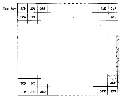
To write a particular character into a character cell in the display the user must write the ASCII code, or whatever, for that character in the correct memory location. For example, if it was required to write the character “W” in the bottom row third column then the ASCII code 57 (for W) should be placed in memory location 3E2. If you use TANBUG’s memory modify command M to load characters into the display remember that the display scrolls automatically and the character may be output onto a different row than intended.
Memory mapping of the microtan 65 is controlled on-board by three wire links, when used without the TANEX expansion board. As there is only 1K RAM, 1K ROM and 6 I/O locations on the microtan 65 each of the three are allowed to repeat through defined areas of the 64K address space to simplify design. The address map is represented diagramatically below.
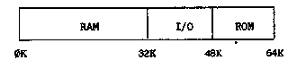
As can be seen the address space is divided into only three blocks and therefore only two bits of the address bus are necessary to control this map. The two bits used for memory mapping are the most significant address bits A15 and A14. Three links are used to wire in this address map on the microtan 65. When TANEX is used however, all memory mapping is controlled on the TANEX board and not on the microtan 65. To modify the microtan 65 it is only necessary to cut these three links.
RAM and ROM hardware is of really no consequence to the user but a knowledge of the on-board I/O ports is useful. There are six peripheral ports used on the microtan 65 cpu board and these control graphics on and off, keyboard read and write, keyboard interrupt flag clear and delayed non-maskable interrupt (used for single instruction and breakpoints). Each one of these will be taken in turn:
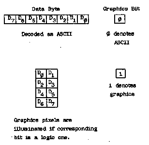
a) Graphics on and off: The display refresh controller reads the display memory a byte at a time and interprets the bottom seven bits of each byte to be an ASCII coded character. There is however a ninth bit which can only be written to by the cpu. This ninth bit comes from the 2102 1K x 1 bit RAM chip in the graphics option. If at a certain display location the ninth bit, or graphics bit, is a logic one the data byte read is not decoded as an ASCII character but is instead used to build up a graphics block of 2 x 4 pixels, in the character cell position.
The graphics on and graphics off I/O ports control an R-S flip-flop, the output of which is the data input to the 2102 RAM chip. Therefore if the graphics flip-flop is in the on position each character written to the display memory will be decoded as a graphics character. Because the cpu cannot read the graphics bit directly it is not possible to scroll displays containing graphics. As displays containing graphics are rarely scrolled anyway this should not prove to be too much of a handicap.
The operations required to write graphics characters to the display is to firstly turn the graphics on by executing the assembly code instruction LDA BFF0. Each character then written to display will be a graphics character until graphics are turned off by executing the assembly code instruction STA BFF3.
b) Keyboard read, write and interrupt clear: There is both an input and output port on the keyboard socket. The output port is used only for strobing the 20 key keypad. This output port is used by executing the assembly code instruction STA BFF2. The input port is used for both types of keyboard. When using the alphanumeric keyboard the strobe from the keyboard is used to clock a flip-flop (the keyboard interrupt flip-flop). The output of this flip-flop is the keyboard interrupt flag and forms the eight input bit to the keyboard input port. If interrupts are enabled in the cpu then an interrupt will be generated by the keyboard strobe. Reading the keyboard input port will then allow the cpu to test whether or not the interrupt was generated by the keyboard or some other device. If interrupts are not enabled then the keyboard interrupt flag will still be set but will not generate an interrupt. It is possible to read the flag by reading the keyboard interrupt port, thus a strobe from an alphanumeric keyboard can be detected either by an interrupt or by software polling. Which ever technique is used though it will be necessary to reset the keyboard interrupt flag after it has been set and detected in order that is its ready to register a further keyboard strobe. To reset the keyboard interrupt flag the assembly instruction STA BFF0 should be executed. The keyboard port is read by the instruction LDA BFF3.
c) Delayed non-maskable interrupt: This facility is used by the monitor program TANBUG when executing single instructions and breakpoints. It should not be used in a used program. Users who will contemplate using the non-maskable interrupt in special applications will probably not be using TANBUG. In these cases the link LKNMI should be broken and the non-maskable interrupt may be driven via the board connector.
CHAPTER 6: TANBUG
The TANBUG monitor program is located in 1K bytes of read only memory (ROM) at the top of the address space i.e. pages 252-255. It contains facilities to enter, modify, run and debug programs. This chapter of the manual gives full details of the command facilities and subroutines available to the user.
TANBUG will only operate in the memory map of the microtan system, it is not a general purpose 6502 software and has been specifically written for microtan. Locations F7F7, F7F8 and F7F9 are reserved for a jump to an expansion monitor ROM which is positioned on the expansion board, more about this later. Locations 200-3FF i.e. pages 2 and 3 are the visual display memory -TANBUG writes to these locations whenever a command is typed to the monitor. Locations 100-1FF i.e. page 1, are used as the stack by the microprocessor. Since the stack is of the push down variety it follows that the whole of the page will not be used as stack storage in the majority of programs. TANBUG requires to use locations 1F0-1FF as stack storage (only 16 locations). The rest of this area is free for user programs. Locations 40-FF are also available as user RAM, the preceding locations 0-3F being reserved for use by TANBUG. User programs which do not use the stack may therefore be loaded anywhere i.e. the area 40-1EF. For user programs which do use the stack, the user must calculate how many stack locations are required and reduce the upper limit accordingly.
TANBUG contains coding to automatically identify whether the keypad or full ASCII keyboard is connected to the keyboard socket. This coding is executed every time a reset is issued, and thereafter a sequence of code particular to the keyboard type in use is executed. Reset must therefore always be issued after changing the keyboard type.
When using an ASCII encoded alphanumeric keyboard monitor commands are typed in as shown in this chapter. There is however, no reset key on an ASCII keyboard, one must be fitted as shown in the chapter describing assembly of the microtan kit. TANBUG drives this type of keyboard in the interrupt mode.
The keypad is used somewhat differently, its layout being shown below.
| SHIFT | DEL LF | SP CR | RST |
| M C | G D | S E | N F |
| P 8 | ESC 9 | B A | L B |
| 4 | 0 5 | C 6 | R 7 |
| 0 | 1 | 2 | , 3 |
TANBUG interrogates the keypad for a depressed key, then translates the matrix encoded signal into an ASCII character which it puts up on the visual display just as if the equivalent key were depressed on an ASCII encoded keyboard. Because of the limited number of keys it has been necessary to incorporate a shift function on the keypad. So, to obtain the character P for example, the user presses and releases SHIFT, then depresses and releases P. The SHIFT key contains a self cancelling facility - if the user presses SHIFT twice in succession the pending shift operation is cancelled. So as an example, using the two keys SHIFT and 8 the operations SHIFT P yields P on the display. SHIFT SHIFT P yields 8 on the display. Other special purpose keys on the keypad are RST, which issues a reset to the microtan, and DEL which deletes the last character typed. Repeated deletes erase characters back to the beginning of the line.
From now on in this chapter the microtan will be treated as having one type of keyboard only, since all functions required can be derived by depressing the appropriate key or keys on whatever is used - keyboard or keypad.
Having described some of the background to TANBUG it is now possible to describe the commands and syntax of TANBUG i.e. how to use it. An example is shown later on. All numerical values of address, data and monitor command arguments are in hexadecimal. The symbol <CR> means on depression of the carriage return key, <SP> the space key or bar, <ESC> the escape key (ALT on some keyboards) and <LF> line feed. In all examples, text to be typed by the user will be underlined, while TANBUG responses will not. indicates the cursor. <ADDR> means a hexadecimal address, <ARG> means hexadecimal data and <TERM> means one of terminators <CR>, <SP>, <ESC> or <LF>.
All commands are of the form
<COMMAND><TERM> or <COMMAND><ARG><TERM> or <COMMAND><ARG>, <ARG><TERM> or <COMMAND><ARG>, <ARG>, <ARG><TERM>
where <COMMAND> is one of the mnemonic commands and <ARG> is a hexadecimal argument applicable to the command being used. The required argument is defined for each command. It should be noted at an early stage that the longest argument will contain 4 hexadecimal characters. If more are typed all but the last 4 are ignored. As an example consider the memory modify command M12340078 <CR>. In this case location 0078 will be modified or examined as all but the last 4 characters are ignored.
<TERM> is one of the terminating characters <CR>, <SP>, <LF> or <ESC>. In fact TANBUG accepts any of the “control” characters (HEX code 0-20) as terminator. TANBUG will reply with a? if an illegal command is encountered.
Starting the monitor TANBUG:
Press the RST key on the keypad or the reset key or button connected to the microtan. TANBUG will scroll the display and respond with
TANBUG
Note that on initial power up the top part of the display will be filled with spurious characters. These will disappear as new commands are entered and the display scrolls up. On subsequent resets the previous operations remain displayed to facilitate debugging.
Memory modify/examine command M:
The M command allows the user to enter and modify programs by changing the RAM locations to the desired values. The command also allows the user to inspect ROM locations, modify registers etc. To open a location type the following
M <ADDR><TERM>
TANBUG then replies with the current contents of that location. For example to examine the contents of RAM location 100 type M100<CR> TANBUG then responds on the display with
M100,0E,
assuming the current contents of the location were 0E.
There are now several options open to the user. If any terminator is typed the location is closed and not altered and the cursor moves to the next line scrolling up the display by one row. If however, a value is typed followed by one of the terminators <CR>, <LF> or <ESC> the location is modified and then closed. For example using <CR>
M100,0E, FF
location 100 will now contain FF. If however <SP> is typed, the location is re-opened and unmodified.
M100,0E, FF M0100,0E,
This facility is useful if an erroneous value has been typed. The terminators <LF> and <ESC> modify the current location being examined, then opens the next and previous locations respectively i.e. using <LF>
M100,0E, FF M0101,AB,
and using <ESC>
M100,0E, FF M00FF,56,
Using <LF> makes for very easy program entry, it only being necessary to type the initial address of the program followed by its data and <LF>, the responding to the cursor prompt for subsequent data words.
NOTE that locations 1FE and 1FF should not be modified. These are the stack locations which contain the monitor return addresses. If they are corrupted TANBUG will almost certainly “crash” and it will be necessary to issue a reset in order to recover.
List command L:
The list command allows the user to list out sections of memory onto the display. It is possible to display the contents of a maximum of one hundred and twenty consecutive memory locations simultaneously. To list a series of location type
L <ADDR>, <NUMBER><TERM>
where <ADDR> is the address of the first location to be printed and <NUMBER> is the number of lines of eight consecutive locations to be printed. TANBUG pauses briefly between each line to allow the user to scan them. For example, to list the first 16 locations of TANBUG (which resides at FC00-FFFF) type LFC00,2<CR>. The display will then be
LFC00,2 FC00 A2 FF 9A E8 86 17 20 B7 FC08 FF 8D F3 BF A2 0E BD DF
If zero lines are requested (i.e. <NUMBER> = 0) then 256 lines will be given.
Go command G:
Having entered a program using the M command and verified it using the L command the user can use the G command to start running his own program. The command is of the format G <ADDR><TERM>. For example, to start a program whose first instruction is at location 100 type G100<CR>. When the user program is started the cursor disappears. On a return to the monitor it re-appears.
The G command automatically sets up two of the microprocessors internal registers
a) The program counter (PC) is set to the start address given in the G command b) The stack pointer (SP) is set to location 1FF.
The contents of the other four internal registers, namely the status word (PSW), index X (IX), index Y (IY) and accumulator (A), are taken from the monitor pseudo registers (described next). Thus the user can either set up the pseudo registers before typing the G command, or use instructions within his/her program to manipulate them directly.
Register modify/examine command R:
Locations 15 to 1B within the RAM reserved for TANBUG are the user pseudo registers. The user can set these locations prior to issuing a G command. The values are then transferred to the micro-processors internal registers immediately before the user program is started. The pseudo register locations are also used by the monitor to save the user internal register values when a breakpoint is encountered. These values are then transferred back into the microprocessor when a P command is issued, so that to all intents and purposes the user program appears to be uninterrupted.
The R command allows the user to modify these registers in conjunction with the M command. To modify/examine registers type R<CR> and the following display will appear (location 15 containing 00 say)
R M0015,00,
Now proceed as for the M command.
Naturally the M command could be used to modify/examine location 15 without using the R command - the R command merely saving the user the need to remember and type in the start location of the pseudo registers. Pseudo registers locations are as follows.
| Location | Function |
|---|---|
15 | Low order byte of program counter (PCL) |
16 | High order byte of program counter (PCH) |
17 | Processor status word (PSW) |
18 | Stack pointer (SP) |
19 | Index X (IX) |
1A | Index Y (IY) |
1B | Accumulator (A) |
Two typical instances of the use of the R command are:-
a) Setting up PSW, IX, IY and A before starting a user program. b) Modifying registers after a breakpoint but before proceeding with program execution (executing the P command) for debugging purposes.
Note that when modifying registers in case (b) care must be taken if PCL, PCH or SP are modified, since the proceed command P uses these to determine the address of the next instructions to be executed (PCL, PCH) and the user stack pointer (SP).
Single instruction mode S:
Single instruction mode is a very powerful debugging aid. When set TANBUG executes the user program one instruction at a time, re-entering the monitor between each instruction and printing out the status of all of the microprocessor’s internal registers as they were after the last instruction executed in the user program. The S command is used in conjunction with the proceed command P and the normal mode command N. Examples are given in the description of the P command.
Normal mode command N:
The N command is the complement of the S command and is used to cancel the S command so that the microprocessor executes the user program in the normal manner without returning to the monitor between each instruction. Reset automatically sets the normal mode of operation.
Proceed command P:
The P command is used to instruct TANBUG to execute the next instruction in the user program when in single instruction mode. Pseudo register contents are transferred into the microprocessors internal registers and the next instruction in the users program is executed. The monitor is then re-entered. P may also be used with an argument thus P <NUMBER><CR> where NUMBER is less than or equal to FF. In this case the program executes the specified number of instructions before returning to the monitor.
Each time the monitor is re-entered after execution of an instruction or instructions, the status of the microprocessor internal registers as they were in the user program are printed across the screen in the following order:
Address of next instruction to be executed. Processor status word. Stack pointer. Index register X. Index register Y. Accumulator.
Note that these are in the same order as the pseudo registers described earlier.
Whenever the user program is entered, the cursor is removed from the display. Whenever the monitor is entered, the cursor returns to the display as a user prompt. While in the monitor between user instructions, any monitor command can be typed. A program must always be started by the G command, then P used if in single instruction mode. A P command used before a G command is issued is likely to cause a program “crash” and should not be attempted.
As an example consider the simple program which repeatedly adds 1 to the accumulator.
| Address | Data | Mnemonic | Comment |
|---|---|---|---|
100 | 69 | ADC #1 | add 1 to acc |
101 | 01 | ||
102 | 4C | JMP 100 | |
103 | 00 | ||
104 | 01 |
Set the single instruction mode and start the program. The user may wish to initially set the accumulator to 00 by using the M command.
S G100 0102 20 FF 00 00 01
TANBUG then responds with the characters shown above.
0102 is the address of the next instruction to be executed. 20 is the processor status word value. FF is the low byt value of the stack pointer. The high byte is always set to 1, the stack is therefore pointing at location 1FF. 00 is the value of the index X register. 00 is the value of the index Y register. 01 is the value of the accumulator. It is a 1 as 1 has been added to the accumulator and it is assumed that the user cleared the accumulator before starting the program.
Since the cursor has re-appeared, TANBUG is ready for any monitor command. For example, registers or memory locations can be modified, or the program may be re-started from scratch by typing G100<CR> again. If the user wishes to continue then type P<CR>. The resulting display is
S G100 0102 20 FF 00 00 01 P 0100 20 FF 00 00 01
Since the instruction at location 102 was “Jump to 100”, the status print out shows that this has indeed occurred. Registers, since they were not modified by any program instruction, remain unchanged. To proceed further type P<CR> again.
S G100 0102 20 FF 00 00 01 P 0100 20 FF 00 00 01 P 0102 20 FF 00 00 02
The add instruction has been executed again, so the accumulator has incremented by 1 to become 2. Now typing P4 <CR> gives a display.
S G100 0102 20 FF 00 00 01 P 0100 20 FF 00 00 01 P 0102 20 FF 00 00 02 P4 0102 20 FF 00 00 04
TANBUG allowed execution of 4 instructions before again returning to the monitor. The 4 instructions were 2 add instructions and 2 jump instructions thus giving the accumulator the value 4.
By typing N<CR> then P<CR> removes the single instruction mode and causes the program to proceed. It now does not return to the monitor but continues to race around this small program loop continually adding and jumping back. There is no way to exit from this trivial program except by a microprocessor reset or, if using an alphanumeric keyboard, by typing ESC.
It can be seen that the S and P commands are particularly useful when tracing a program which contains instructions that transfer program control e.g. jumps, branches and subroutines, since these commands allow the user to interrogate the order of execution of his/her program.
Breakpoint command B:
A breakpoint is a complementary debugging aid to single instruction mode. Instead of stepping singly through all instructions in a program, the breakpoint facility allows the user to specify the address at which he requires the monitor to be re-entered from his/her program. As an example, consider a long program in which a fault is suspected to exist near the end. It would be very tedious and time consuming to single step through the program to the problem area. A breakpoint can be set just previous to where the fault is suspected to exist and the program started with the G command. Normal execution occurs until the breakpoint is reached, then the monitor is re-entered with the same status print-out as for single instruction mode. Any monitor commands can then be used and the program continued.
The format of the breakpoint command is
B <ADDR>, <NUMBER> <CR>
where <ADDR> is the address of any instruction OPCODE (but not argument), <NUMBER> is any number from 0-7 defining one of 8 breakpoints. B <CR> removes all breakpoints. As an example consider the following program
100 | E8 | LOOP: | INX |
101 | C8 | INY | |
102 | C9 01 | ADC #1 | |
104 | 4C 00 01 | JMP LOOP |
Firstly set index X, index Y and the accumulator to 00 using the R command. To set breakpoint 0 at the jump instruction and start the program type B104,0<CR>. The display will then be
B104,0 G100 0104 20 FF 01 01 01
The jump instruction was reached and the breakpoint re-directed control back to TANBUG. If it were required, single instruction mode could be set for further debugging. However, assume that we wish to execute the loop again by typing P<CR>.
B104,0 G100 0104 20 FF 01 01 01 P 0104 20 FF 02 02 02
The proceed command P has gone once through the breakpoint and then re-entered the monitor. If P<NUMBER><CR> was typed it would have proceeded through the breakpoint <NUMBER> times.
Up to 8 breakpoints can be set at 8 different locations. The B <CR> command removes all breakpoints. A single breakpoint can be removed by setting its address to 0. For example, imagine a breakpoint is set as follows; B102,2, and it is subsequently wished to remove it but leave any others unaltered; type B0,2<CR> to remove it.
Caution. The breakpoint system works by replacing the users instruction with a special instruction (BRK) whose opcode is 00. Replacement is carried out when G or P is typed. On return to the monitor the original opcode is replaced. It is therefore possible to corrupt the user program under some circumstances. The following points should therefore be observed:
a) Breakpoints must only be set at the opcode part of a user instruction and nowhere else. b) If the user program utilises the BRK instruction as part of the user code, then the user must have his own special interrupt routine and cannot use breakpoints. c) If breakpoints are set in the user program and a reset is issued while the microprocessor is executing the user program rather than the monitor, the breakpoints are lost and those locations at which breakpoints were set in the user program will be corrupted. These locations must be re-entered using the M command before restarting the user program. d) Setting more than one breakpoint at the same address causes the user program to be corrupted. e) To use breakpoints, the user must not have modified the interrupt link, i.e. the interrupt code within TANBUG must be executed.
The status of breakpoints may be inspected by using the M command to examine the breakpoint status table. This is located in RAM locations 20-2F and are as follows:
| Address | Contents |
|---|---|
20 | PCL B0 |
21 | PCH B0 |
22 | PCL B1 |
23 | PCH B1 |
24 | PCL B2 |
25 | PCH B2 |
26 | PCL B3 |
27 | PCH B3 |
28 | PCL B4 |
29 | PCH B4 |
2A | PCL B5 |
2B | PCH B5 |
2C | PCL B6 |
2D | PCH B6 |
2E | PCL B7 |
2F | PCH B7 |
For example, typing M20<CR> followed by <LF> gives
M20,00, M0021,01,
This indicates that breakpoint 0 is set to location 100 by taking the contents of location 20 as PCL and of location 21 as PCH. If the breakpoint is set at location 0 then this particular breakpoint is disabled.
Offset command O:
The offset command O is a program writing aid. It calculates branch offsets for the user for incorporation as arguments in branch instructions. Consider the example:-
100 | E8 | LOOP: | INX |
101 | C8 | INY | |
102 | 69 | ADC #1 | |
103 | 01 | . | |
| . | |||
| . | |||
120 | D0 | BNE LOOP | |
121 | (branch argument) |
To calculate the number to enter into location 121 is quite tedious without a facility such as the O command. It is used with the following format.
O <ADDR. OF BRANCH OPCODE><ADDR. OF DEST.><CR>
and in this case it would be necessary to type O120,100<CR>. The display would be
O120,100 = DE
DE is the number that should be entered into location 121 such that if the BNE instruction is true the program counter will jump to the label LOOP.
Note that the maximum branch range is 7F forwards and backwards. If the range is exceeded a? is displayed.
Copy command C:
The copy command allows copying of the contents of one block of memory to another. Its format is
C <START ADDR. SOURCE><END ADDR. SOURCE><START ADDR. DEST>
Suppose it is required to copy the block of data in locations FC00-FD00 into a block starting at location 200. This may be achieved by typing CFC00,FD00,200<CR>. The display will be
CFC00,FD00,200
As 200 is the starting address of the display memory the user will notice that the top half of the screen has been over written with all sorts of weird and wonderful characters. What this example has done is to take the first 256 bytes of TANBUG and copy them into the top half of the display. The display then scrolled having the top 7 rows filled with these characters.
Breakpoints and the ESC key
If an alphanumeric keyboard is being used, depression of the ESC key (ALT on some keyboards) will cause a re-entry into the monitor from the user program. This is possible because the alphanumeric keyboard is interrupt driven. For example, if the trivial program
100 | 69 | LOOP: | ADC #1 |
101 | 01 | ||
102 | 4C | JMP LOOP | |
103 | 00 | ||
104 | 01 |
has been started by typing the G command the program continues to loop around continuously with no exit path to the monitor, except by issuing a reset. Instead of a reset the user can press the ESC key, TANBUG responding thus
0100 20 FF 01 01 01
Using the ESC key has caused a breakpoint to be executed and the monitor invoked. The register print-out above is only typical, the value of each beaing that when the ESC was depressed. Any monitor command may now be typed, for example P causes the user program to proceed once again.
The ESC facility is most useful in debugging where the user program gets into an unforseen loop where breakpoints have not been set. It enables the user to rejoin the monitor withour using reset and losing the breakpoints that have been set. Notes:
a) The ESC facility is only implemented on interrupt driven keyboard i.e. alphanumeric ASCII keyboards, and is not implemented on the keypad. b) Interrupts must be enabled for the ESC facility to operate. TANBUG enables interrupts when entering a user program, therefore do not disable interrupts if the ESC facility is required. c) The user must not have modified the interrupt jump link. TANBUG’s interrupt code must be executed.
USER SUBROUTINES (I haven’t typed this part, but instead OCR’ed it, so there are some glitches….)
Certain input/output subroutines are available to the user. Since these rely on a standard display format, this will be described first, followed by the user subroutine descriptions.
Display format
TANBUG uses the bottom line of the display for all text operations. Initially the cursor is at the left hand edge of the screen, and moves gradually to the right as a line is filled. When either a carriage return is output, or the bottom line overflows, the display is scrolled (all lines shift up one row) and the bottom line becomes available for more output. Therefore the cursor always remains on the bottom line. However, there is no reason why users should restrict themselves to this mode of operation unless they intend to use TANBUG’s subroutines to control the display in their own programs. It should be noted that the display memory is read/ write memory and may be used as a character buffer prior to processing thus saving RAM locations for a user program.
Subroutine POLLKB
Subroutine POLLKB is used to interrogate the keyboard for a typed key. (Appropriate software for the type of keyboard in use is automatically set-up by TANBUG when a reset is issued). On exit from the subroutine the RAM location labelled ICHAR (address W01) contains the ASCII code of the character typed, whether it is typed on the keypad or on an alphanumeric keyboard. When using the alphanumeric keyboard, interrupts must be in the enabled state. As an example consider the user code
- C LI enable interrupts
- JSR POLLKB poll the keyboard
- LDA ICHAR load acc. with character The sequence of operations here are
- Enable interrupts so that alphanumeric keyboard may be interrogated.
- The program loops around within the POLLKB sub- routine until a key is pressed.
- The program exits from POLLKB with the -ASCII code for the key pressed in the location label-led ICHAR. The accumulator is loaded with this value. Notes: Address of subroutine POLLKB is FDFA. Address of ICHAR is W01. The registers IX, IY and A are corrupted, therefore the user must save and restore their values if necessary.
Subroutine OUTPCR
This subroutine causes the display to scroll up one line by out- putting a carriage return to it. It also reinstates the cursor, which is switched off when a user program is started. This sub- routine should be called in a user program prior to any display input or output to clear the bottom line. Notes: Address of subroutine OUTPCR is FE73. Registers IX and IY are unaffected. Register A is corrupted and must be saved if re quire d.
Subroutine OPCHR
This subroutine is called to output a character held in the accumulator, to the display. The cursor, obliterated on a user program start, is re-instated. As an example, consider the code
LDA#30 JSR OPCHR LDA#31 JSR OPCHR 6-17
Since 30 is the ASCII code for the character “Oll and 31 is the ASCII code for the character 11111, the result (assuming this is the first call to this subroutine) on the botbom line of the display is Oil Repetitive calls of OPCHR will fill the bottom line of the display with the appropriate characters. When the end of the line is reached, OPCHR scrous the display up one line and then writes characters in the newly vacatbd bottom line and so on. Notes: Address of subroutine OPCHR is FE75. Registers IX and IY are unaltered. Register A is corrupted and must be saved if re quire d.
Subroutine HEXPNT
Subroutine HEXPNT takes a binary value from the accumulator and outputs it as two hexadecimal characters on the display. Consider the code
PHA save A on stack JSR OUTPCR scroll display PLA recover A JSR HEXPNT output A in hex JSR OUTPCR scrol 1 display
This code will display the contents of the accumulator as two hex characters. For example if the accumulator contained the value 2C the resulting display would be 2C
Notes: Address of subroutine HEXPNT is FFOB. Register IY is unaltered. Registers IX and A are corrupted and must be saved if re quire d.
Subroutine HEXPCK
This subroutine reads hex characters from the bottom line of the display and packs them up into two eight bit binary values,
enabling a sixteen bit word to be assembled. It is useful for incorporation into programs which require numerical keyboard input. Usually POLLKB is used in conjunction with OPCHR to enter data to the display, then HEXPCK called when a carriage return is encountered. The following user code could be used to do this
JSR OUTPCR scrol 1 display NXTCHR: JSR POLLKB wait for chwacte r LDA ICHAR put it in A CMP# $0D carriage return? EE Q GOPACK yes, p ack it JSR OPCHR else store in display JM P NXTCHR get next character
- GOPACK: LDY# 00 set IY to first char.
- JSR HEXPCK pack it
In this example the subroutine is used in the following way:
- Set IY with the character position at which packing is to start. The left most location of the bottom line corresponds to setting IY tc) 0. The next location corresponds to IY equal to 1 etc.
- Call HEXPCK. Characters are packed until a character other that 0-9 or A-F is encountered; an exit then occurs.
- Continue into the user code where the values of HXPKL and HXPKH will be read. For example, packing 1 CR gives HXPKL = 1 and HXPKH = 0. Packing FEDC CR gives HXPKL = DC and HXPKH = FE. Packing FEDCBA CR gives HXPKL = BA and HXPKH = DC, i.e. if more than four hexadecimal characters in succession are encountered then the last four are packed. Additionally, two flags in the processor status word (PSW) are used to indicate exit conditions. The zero flag Z is clear if the terminating character is the cursor (ASCII code FF), set otherwise. The overflow flag V is set if there w as one or more hex characters, clear if the first character encountered by the subroutine was not a hexadecimal character. Notes: Address of subroutine HEXPCK is FF28. Address of HXPKL is
is 0013 and HXPKH is 0014. Registers IX, IY and A are all corrupted and must be saved if necessary.
INTERRUPTS
TANBUG uses both the maskable and non-maskable interrupts. How- ever, means have been provided tc) access the interrupts via both hardware and software. Of necessity user interrupts may, in some cases, place restrictions on certain monitor commands.
The maskable interrupt
When TANBUG is initialised by a reset, certain RAM locations are set up to link through the interrupts for monitor use. These locations are labelled INTFS1, INTFS2, INTFS3 and INTSL1. When a maskable interrupt occurs, the following sequence of events is obeyed (assuming the RAM locations mentioned above have not been modified). a) The program jumps to INTFS1 in RAM. b) The locations INTFS1, INTFS2 and INTFS3 contain the instruction JMP KBINT. The program therefore jumps to KBINT which resides in the monitor ROM. c The monitor software looks to see what caused the interrupt. If a BRK instruction, then the break- point code is executed. If a keyboard interrupt, location ICHAR is updated with the new ASCII character which is read from the keyboard I/O port. d) If the interrupt is caused by anything other than a BRK instruction then the monitor jumps to location INTSL1. e) Normally INTSLL contains an RTI instruction - the program would then return to where it was interrupted. It can therefore be seen that the user can implement his/her own interrupt service routines in two ways.
- A fast interrupt response by modifying the locations INTFS1, INTFS2 and- INTFS3 to jump to the user interrupt service code. In this case bre ak- points and the ESC command cannot be used unless the u–er program jumps back to the monitor service
routine after executing its own code. 2) A slower interrupt response by modifying INTSL1, INTSL2 and INTSL3 to jump to user service routine, after executing the monitor service routine. The RAM locations INTSL1, INTSL2 and INTSL3 would be modified to contain the instruction JMP USER. This method places no restrictions on monitor commands.
A number of things should be noted when using interrupts: a) An RTI instruction must always occur at the end of user code to return the program to the point at which it was interrupted, unless the user code jumps back to the monitor service routine. b) If a reset it issued, the INTFS and INTSL locations are set back to their monitor values by TANBUG, and the user has to reset them. c) If any microprocessor internal registers are used in the user interrupt service routine, they must be saved before modification and restored before the RTI instruction, i.e. on return to the monitor the registers IX, IY and A must contain the same values as they had on entry to the user routines. d) The interrupt jump locations should be modified by instructions in the user program at run time and not by the use of the M command. This is because TANBUG softwar-- uses keyboard interrupts. If using an alternative link at INTFS1, no break- points c an be set. e Addresses of RAM locations are; INTFS1 = OW4, INTFS2 = OW5, INTFS3 = ON6, INTSLI 0010, INTSL2 = 0011, INTSL3 = 0012.
The non-maskable interrupt
The non-maskable interrupt vector is accessed in the same way as explained for the maskable interrupt. The user can obtain access by modifying locations NMIJP, NMIJPL and NMIJP2. Note that single instruction mode will be inoperative and that breakpoints will be destructive, i.e. they are destroyed when they have been executed once and replaced with the original code. Addresses of RAM locations are; NMIJP = OW7, NMIJPL and NMIJP2 = W09.
ERROR LINKING
It will be noted that TANBUG displays a question mark whenever an illegal command is typed. In order to allow future expansion of the monitor, an error link to memory external to the monitor ROM’s is incorporated.
When an error occurs the following sequence of events is initiated: a) The program jumps to F7F7. b) With no expansion board (TANEX) present the address F7F7 (outside TANBUG space) is decoded as address FFF7 (inside TANBUG space). c) A question mark is printed.
With TANEX present, a special link is incorporated to return the program to the monitor. The user may remove this link and insert an EPROM in the position which includes the address F7F7 containing the code JMP USERCODE at address F7F7, where USERCODE may contain software to deal with any extra commands the user wishes to add to the monitor. Note that this facility will be used by future TANGERINE software.
There are two methods of returning to the monitor from external code:
- The instruction RTS at the end of the user code returns to the monitor, gives a carriage return then continues looking for commands.
- The instruction JMP FFF7 returns tc) the monitor, giving a question mark on the display.
EXAMPLE OF TANBUG’s USE
The following, simple example program clears the screen by calling OUTPCR F times, then slowly fill the screen with asterisks. It is used as an example to demonstrate the use of some of TANBUG’s commands. Deliberate errors are later writben into the program to demonstrate TANBUG’s fault finding capabilities.
The first step in writing a program is to produce a flowchart of program execution. The second step is to write the program in assembly language code using the instruction mnemonics. The third
step is to look up and write the op-codes and arguments for each instruction. At this stage the branch code arguments will be left blank and TANBUG’s 0 command used.
The flowchart and program listing now follows.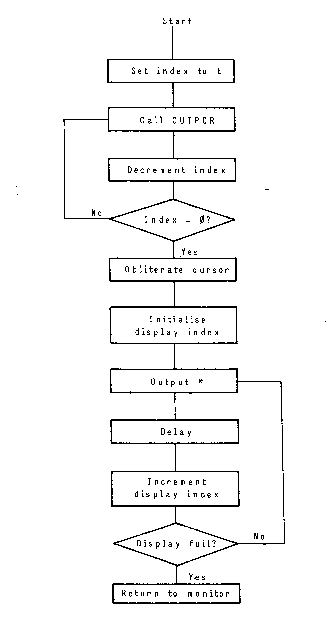
Example program listing
0050 00 00 VDUIND: 0; display index
0052 AO OF START: LDY# F;set Y index
0054 20 73 FE SCRAG: JSR OUTPCR;carriage return
0057 88 DEY;do E times
0058 10 (arg 1) BPL SCRAG
005A A9 20 LDA# 20;load A ascii space
005C 8D EO 03 STA 3EO;obliterate cursor
005F, A9 00 LDA# 0;set display index
0061 85 50 STA VDUIND
0063 A9 02 LDA# 2
0065 85 51 STA VDUIND+L
0067 AO 00 CONT: LDY# 0;clear Y index
0069 A9 2A LDA# 2A;set ascii
006B 91 50 STA (VDUIND),y
006D A2 OF LDX# F; delay loop
006F AO FF LDY# FF
0071 88 DECIT: DEY
0072 DO (arg 2) BNE DECIT
0074 CA DEX
0075 DO (arg 3) BNE DECIT
0077 18 CLC;inc display index
0078 E6 50 INC VDUIND
007A Do (arg 4) BNE NOMSB
007C E6 51 INC VDUIND+L
007E A5 51 NOMSB: LDA VDUIND+L;top of display?
0080 C9 03 CMP# 3
0082 Do (arg 5) BNE CONT; no - continue
0084 A5 50 LDA VDUIND
0086 C9 FF CMP# FF
0088 DO (arg 6) BNE CONT; double prec. cmp.
008A 00 BRK;return to monitor
Program entry is performed using the M command. For the time being set the branch arguments (arg I - arg 6) to 00, these c an be altered when calculated, using the 0 command.
Once the program is entered the branch offsets are calculated. The first is arg 1 which has an opcode address of 0058 and branches to the label SCRAG at location 0054. By typing 058,54<CR> TANBUG print3 out the value of arg 1 as FA. This may now be placed in location 0059 using the M command. By repeating the exercise for the other five arguments it will be found that location 0073 should contain FD, 0076 should contain FA, 007B should contain 02, 0083 should contain E3 and 0089 should contain DD.
The program will now run if it has been entered correctly. To start the program type G52<CR> since the first instruction of the program is at location 0052. When the screen is full of asterisks the program exits to the monitor. Alternatively, if an alphanumeric keyboard is being used, depression of the ESC key causes an exit to the monitor. If the program does not run correctly then it may be necessary to issue a reset in order to regain control. The program can be listed by typing L50,8<CR> yielding a display of L50,8 0050 00 00 AO OF 20 73 FE 88 0058 10 FA A9 20 8D EO 03 A9 0060 00 85 50 A9 02 85 51 AO 0068 00 A9 2A 91 50 A2 OF AO 0070 FF 88 DO FD CA DO FA 18 0078 E6 50 DO 02 E6 51 A5 51 0080 C9 03 DO E3 A5 50 C9 FF 0088 DO DD 00 XX XX XX XX XX I providing the program has been correctly entered (XX indicates any value as these locations are not part of the program). If the program failed to run carefully check the listing from the L command with the program listing and correct any errors with the M command.
Having got the program working it is now possible to introduce a deliberate error to demonstrate the use of breakpoints and the single instruction mode. The error to be introduced is to put the wron value for the branch argument on the first occurrence of the
instruction BNE DECIT; instead of location 73 containing FD change it to F B. Now the register IY will never be zero and the program will loop here. If the program is started now only one asterisk will be printed and then nothing else will happen. Debugging steps are as follows: a) Regain control to the monitor by issuing a reset. b) The first part of the program is being executed correctly as the display scrolls. Furthermore, it is at least getting to location 6B because an asterisk is printed. It would be very tedious to single instruction this far from the beginning because the OUTPCR routine is called sixteen times. Therefore set a breakpoint at location 6D by typing B6D,O<CR>. c) Start the program again by typing G52<CR>. The display scrolls and the status message 006f 31 F F OF 00 2 A 0 D
is displayed. Control is now back in the monitor. d) Set single instruction mode by typing S<CR>. e) Repeatedly typing P<CR> causes single instructions to be executed followed by a status print-out. The following sequence of instructions will be, observed. 006F 21 FF OF 00 2A 0071 Al FF OF FF 2A 0072 Al FF OF FE 2A 006F Al FF OF FE 2A Now if the code were correct the program could not go back to location 6F. In fact, since IY is shown to be FE, the program should have jumped back to location 71. The branch instruction is probably at fault, therefore examine it and its argument using the M command. M72, Do, M0073,FB,m The value in location 73 should be FD, therefore change it by typing FD<CR>. f) Remove single instruction mode and breakpoints by typing N<CR> then B<CR>. g) Restart the program by typing G52<CR>. The program should now run correctly.
Note that when using an alphanumeric keyboard, debugging is slightly easier. When the program sticks in a loop ESC can be used to return to the monitor (provided interrupts have not been disabled). Single instruction mode can then be set to determine the loop in which the program was running.
TABLE OF HEX ASCII CODES
00 NUL
01 Control A Home
02 Control B
03 Control C
04 Control D
05 Control E
06 Control F
07 Control G Bel 1
08 Control H Backspace
09 Control I Horizontal Tab - Cursor Right
OA Control J Line Fee d
OB Control K
oc Control L P age Cle ar - Form Fee d
OD Control M Carriage Return
OE Control N
OF Control 0
10 Control P
11 Control Q
12 Control R
13 Control S
14 Control T
15 Control U
16 Control V
17 Control W
18 Control X
19 Control Y
1A Control Z Vertic al Tab Cursor Up
1B Si
ic S2
1D S3
1E S4
1F S5
Note that the codes 00 - 1F produce special symbols when used
in display memory.
TABLE OF HEX ASCII CODES (CONTINUED)
20 Space 40 @ 60
21 41 A 61 a
22 42 B 62 b
23 f- or 43 c 63 c
24 $ 44 D 64 d
25 % 45 E 65 e
26 & 46 F 66 f
27 47 G 67 9
28 48 H 68 h
29 49 I 69 i
2A 4A i 6A
2B 4B K 6B k
2C 4C L 6C 1
2D 4D m 6D m
2E 4E N 6E n
2F 4F 0 6F 0
30 0 50 p 70 p
31 1 51 Q 71 q
32 2 52 R 72 r
33 3 53 s 73 s
34 4 54 T 74 t
35 5 55 u 75 u
36 6 56 v 76 v
37 7 57 w 77 w
38 8 58 x 78 x
39 9 59 y 79 y
3A 5A z 7A z
3B 5B 7B
3C < 5C 7C
3D 5D 7D
3E > 5E A 7E
3F? 5F 7F or Rubout
TANBUG LISTING
Om NULL: 00;reserved for bpt use
Owl ICHAR: 00; asci-i character
ON2 OCHAR: 00;temp char store
W03 VDUIND: 00; display index
OW4 INTFS1: 00;fast int link
OW5 INTFS2: 00
INTFS3: 00
OW7 NMIJP: 00;nmi link
OW8 NMIJP1: 00
W09 NMIJP2: 00
OMA ICURS: 00;cursor index
OMB ICURSH: 00;cursor index high
moc RUNIND: 00; zero if in user
OND SINGLE: 00; nonzero if sing int3
OOOE PROCED: 00; proceed count
OMF SIMCOM: 00;simple/complex kb
0010 INTSL1: 00; slow int i nk
0011 INTSL2: 00
0012 INTSL3: 00
0013 HXPKL: 00;hexpack low byte
0014 HXPKH: 00
0015 PCLBCK: 00;pseudo reg PCL
0016 PCHBCK: 00 PCH
0017 PSWBCK: 00; PSW
0018 SPBCK: 00;SP
0019 XBCK: 00;IX
001A YBCK: 00;IY
001B ABCK: 00; A
ooic MODADL: 00;temp store
001D MODADH: 00
001E COPL: 00; copy store
001F COPH: 00
0020 BPTLO: 00; bpt status table
0021 00
0022 00
0023 BPTHL: 00
6-30
0024 00
0025 00
0026 00
0027 00
0028 00
0029 00
002A 00
002B 00
002 C 00
002D 00
002E 00
002 F 00
0030 BPTCOD: 00 bpt code store
0031 00
0032 00
0033 00
0034 00
0035 00
0036 00
0037 00
0038 00
0039 00
003A 00
003B 00
003C 00
003D 00
003E 00
003F 00
0100 STKBSE: 00;stack base address
0200 VDUSTT: 00;display scroll labels
0220 VDUFST: 00
0300 VDUMID: 00
0320 VDUTOP: 00
03EO LINBOT: 00
BFFO SGRAPH: 00;I/O ports
KBINCL: 00;alt. tc) SGRAPH
BFF1 SNMI: 00
BFF2 KBWRIT: 00
BFF3 KBREAD: 00
STEXT: 00;alt. to KBREAD
F7 lF7 INPERR: 00;error exit link
;start of main program init. sequence
;program starts here on a reset
FCOO A2FF START: LDX #FF;set stack pointer
FC02 9A TXS;to top of the stack
F C03 EN, INX;enable interrupts in
FC04 8617 STX PSWBCK user prog on a go
;clear breakpoint store as their values will be
;indeterminate on power up.
FC06 2OB7FF JSR BPTCLR;clear breakpoints.
FC09 8DF3BF STA STEXT;set text mode.
now use table to initiate parameters
;note order of table must correspond with the
;order of INTFS1 to ICURSH in ram definitions.
FCOC A20E LDX #E;set index.
FCOE BDDFFF SETUPL: LDA SETUPX; get value.
FC11 9504 STA INTFS1, X; store in ram.
FC13 CA DEX
FC14 10FO BPL SETUP1; do till all done
;
; determine keyboard type and set flag
; note IX=FF.
;
FC16 EO INX
FC17 8E90FO TSFIV: STX KBWRIT;clear kb write latch.
FCLA 8DFOBF STA KBINCL;clear kbint. flag.
FCLD CA DEX
FCLE 8EF2BF STX KBWRIT; write to kb lines.
FC21 EO INX;reset IX.
FC22 ADF3BF LDA KBREAD;read it back.
FC25 1002 BPL KPCPLX;if plus not set-alpha.
FC27 E60F INC SIMCOM;if set then keypad.
FC29 8DFOBF KPCPLX: STA KBINCL;clear kbint.
FC2C BDECFF TBMS: LDA HDR, X; print TANBUG.
FC2F F006 BEQ MONTOR
FC31 2075FE JSR OPCHR;o/p chars until a 0.
FC34 E8 INX
FC35 DOF5 BNE TBMS
;
; monitor at present part of main program.
;
FC37 D8 MONTOR: CLD;set binary mode.
FC38 58 CLI
FC39 20FAEO JS R POLLKB; look at kb.
FC3C A501 LDA ICHAR;get char.
FC3E C921 CMP #21;LT or EQ space-term.
FC40 3006 BMI MONCH1;else o/p char.
FC42 2075FE ISTERM: JSR OPCHR
FC45 4C37FC JM P MONTOR
FC48 204FFC M ONCHL: JSR M ONEN2;call string process.
FC4B A90D RCl: LDA #D;set up CR.
FC4D DOF3 BNE ISTERM;uncond. branch loop.
FC4F Aooo M ONEN2: LDY #0; set IY to zero.
FC51 B10A LDA (ICURS), Y;pick up command.
FC53 AA TAX; store in X.
FC54 Co INY; pee k at ne xt c h ar.
FC55 B10A LDA (ICURS), Y;get it in A.
FC57 1036 BPL MULTI;if -ve was curs or.
FC59 A900 LDA #0;else set A to zero.
FC5B E053 TRYS: CPX #53; was it S?
FC5D D003 BNE TRYM; yes-set GT 0 else skip.
FC5F 860D STX SINGLE
FC61 60 RTS
FC62 E04E TRYN: CPX #4E; was it N?
FC64 D003 BNE TRYP; no-try P.
Chapter 7: Some Games Programs
The legacy table of contents links to this chapter, but no chapter 7 text is present in the source HTML. It has therefore not been reconstructed.
Original manual scan
| Download | Filename | Format | Size | Platform or compatibility | Notes |
|---|---|---|---|---|---|
| Microtan 65 user manual | microtan_users_manual.pdf |
1.34 MiB | PDF reader | Scanned, proofread and corrected by Neal Crook. |