I’ve started by getting the display emulation working, as this and the sound emulation are the biggest unknowns to me. I’m using C and SDL, which seem to be pretty straightforward to use.
The standard Microtan 65 display
The basic Microtan 65 board had a 32×16 character display which could show the standard ASCII character set, but capital letters only. There were two optional extras available, which I am going to include in the emulation:
- Lowercase letters. This was an additional character-set ROM to support lowercase letters.
- “Chunky” graphics. This used RAM and some logic to provide basic graphics support with 64×64 black-and-white pixels.
The display memory is between addresses 0x0200 and 0x03FF, with 0x0200 being the top-left character on the screen and 0x03FF being the bottom-right character. Writing a value to one of the display addresses caused the associated ASCII character to appear at the corresponding location on the screen.
The chunky graphics system was a bit odd to use. The RAM effectively added an extra ninth bit to each display character. If this bit was 1, the character was shown as a chunky graphic. If it was 0, it was shown as an ASCII character.
Unfortunately, it wasn’t possible to read or write to the RAM directly. Instead, the program would read from address 0xBFF0, and all subsequent writes to the display would set the corresponding chunky bit for that character. A write to address 0xBFF3 caused all subsequent writes to the display to clear the corresponding chunky bit.
This meant that the display could show both ASCII and chunky graphics, which was nice. However, because the chunky bit could not be read, if the screen was scrolled, the entire display would turn ASCII or chunky.
Hi-res graphics
Another optional extra was a high-resolution—remember that it’s 1979 when I give you the numbers!—graphics board. This board provided 256×256 black-and-white pixels, but it was possible to have more than one in a system. With three, you could have eight colours, and four would give 16 colours! This was impressive. Trust me. Although it would cost about the same as a small house :)
One problem is that the 8-bit 6502 microprocessor could only access a total of 64 KB and each hi-res board needed 8 KB of RAM, so having four would take up half of the total accessible address space. As the address space included the system ROMs as well as I/O, which is also memory mapped, and program RAM, this was an issue.
To get around this, there was some logic on the backplane which would enable the memory on a single card. This allowed multiple hi-res graphics cards to occupy the same addresses. All you had to do was select the required card before reading or writing it.
The downside, of course, is that writing a single pixel then becomes a long operation:
- Select the “red” card.
- Read the byte containing the pixel that you want to change.
- AND/OR the corresponding bit to get the new value.
- Write the new value to the “red” card.
- Repeat steps 1 through 4 for green, blue and intensity.
This takes quite a bit of time, so it was nice for drawing graphs and things, but it’s never going to play Doom.
Emulation
The emulator supports all of the above.
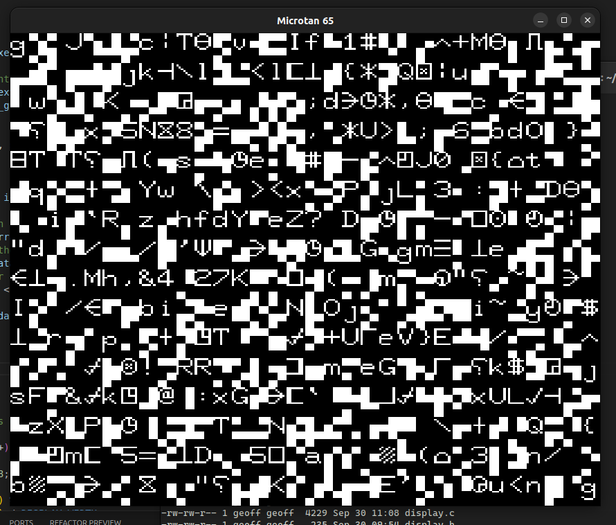
I’ve written the code to support 16-colour hi-res graphics and the standard display. The ASCII characters are taken from a charset.rom file, which is a binary dump of the original full upper/lowercase character ROM. The chunky graphics character equivalents are calculated at runtime.
A display_render function populates a 256×256 array of RGB values. A “white” colour array is created from the standard display, using the RAM between addresses 0x0200 and 0x03FF to provide an index into either the ASCII character set or the chunky characters. The memory of the four hi-res boards is combined to produce a pixel colour, which is ORed with the white array.
I then use SDL_UpdateTexture to create the image texture for the window.
The image below will be somewhat familiar to anyone who used the original system…
Emulator architecture
This is a high-level description of the emulator architecture:
mmu.c— memory management. This will keep a copy of the 64 KB system memory, which will largely be RAM. It will provide functions to read and write the memory and a function to register a device on the memory bus; this registers callbacks associated with an address range. If a memory access occurs within a registered address space, it will call the appropriate callback function to handle it. For example, the display will register a callback associated with0x0200to0x03FF. When a write to this address range occurs, it will set a flag which the main loop can read to determine if the window needs to be rendered. It will also register devices at0xBFF0and0xBFF3which will set or clear a flag to set or clear the chunky graphics bit when display writes occur.display.c— display handler. Keeps its own copies of the RAM for the hi-res boards and renders the display.ay8910.c— AY-8910 sound chip. This will handle everything to do with sound emulation. Again, I’m going to use SDL for the actual audio output.rom.c— all ROMs. Loads all ROM addresses from ROM files: BASIC, XBUG and TANBUG.6522.c— emulates the 6522 I/O chips on the Tanex expansion board. One of these will be used to provide an emulated joystick.6502.c— the CPU emulator.microtan65.c— any bits of hardware not covered by other source files.main.cwill have the usual initialisation and then go into a loop, calling the 6502 emulator and rendering the display until the program is closed. It will also handle the program menu for loading, saving, preferences, etc.